

Mastering Complexity with Advanced 5-Axis CNC Machining
Produce intricate geometries, tighter tolerances, and superior surface finishes with advanced multi-axis CNC machining solutions.
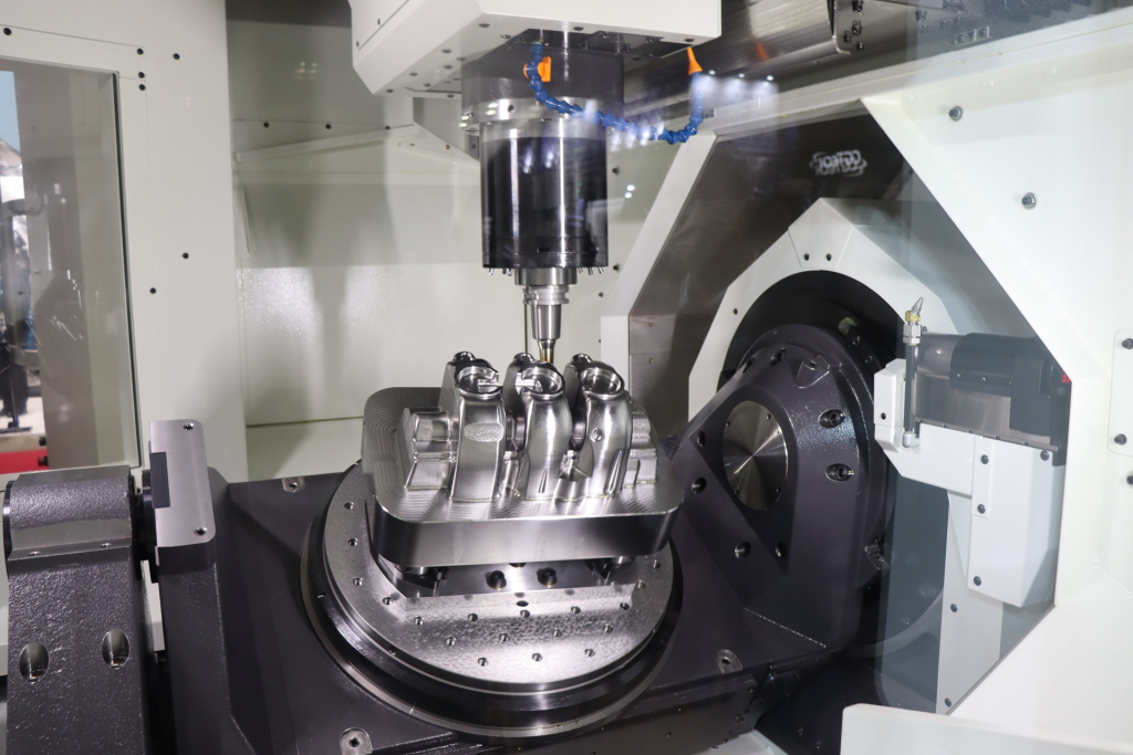
Unlock the Advantages of Advanced 4 & 5-Axis CNC Machining
Our advanced 4-axis and 5-axis CNC machining capabilities enable the production of highly complex, high-precision components for industries such as aerospace, automotive, medical, robotics, and industrial equipment.
Equipped with multi-axis machining centers and supported by experienced engineers and machinists, we manufacture intricate geometries, tight-tolerance parts, and complex surfaces with exceptional accuracy and consistency.
From prototype development to full-scale production, every project is executed with rigorous process control and strict quality standards to ensure reliable performance and superior surface finishes.
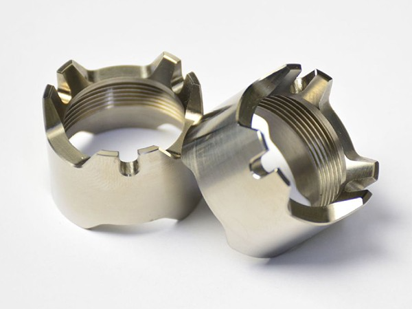
Precision 4 & 5-Axis CNC Machined Part Gallery
Advanced 4-axis and 5-axis CNC machining enable the efficient production of highly complex components with exceptional precision and surface quality. By allowing simultaneous multi-axis movement, these machining technologies reduce setups, improve accuracy, and support intricate geometries that are difficult to achieve with conventional machining methods.
Ideal for complex contours, undercuts, and multi-face machining, our multi-axis CNC capabilities support both rapid prototyping and production across aerospace, medical, automotive, robotics, and industrial applications.
Machining Tolerance Standard
| Tolerance Type | Tolerance Range | Application | Description |
|---|---|---|---|
| Geometric Tolerance | ± 0.005 mm to ± 0.05 mm | Precision parts requiring high form control | Controls the shape, orientation, and position of features to ensure part accuracy. |
| Linear Tolerance | ± 0.001 mm to ± 0.1 mm | General CNC machining | Defines the permissible variation in linear dimensions for mechanical parts. |
| Angular Tolerance | ± 0.1° to ± 1° | Parts with specific angular features | Specifies the allowable deviation in the angle between two surfaces or axes. |
| Surface Finish | Ra 0.8 to Ra 1.6 | Parts requiring smooth surface finish | Defines the roughness of the surface to ensure fit, function, and aesthetics. |
| Position Tolerance | ± 0.01 mm to ± 0.1 mm | Parts with holes or features that require precise location | Specifies the allowable variation in the position of features relative to a datum. |
| Concentricity Tolerance | ± 0.01 mm to ± 0.05 mm | Rotating or symmetrical parts | Ensures that two or more features, such as holes or shafts, are centered within one another. |
| Circular Runout | ± 0.01 mm to ± 0.1 mm | Rotating parts like gears or shafts | Measures the variation in the circularity of a feature as it rotates around its axis. |
| Flatness Tolerance | ± 0.01 mm to ± 0.1 mm | Parts requiring flat surfaces for assembly or function | Controls the deviation from a perfectly flat surface within specified limits. |
Industry Applications of 4-Axis & 5-Axis CNC Machining Services
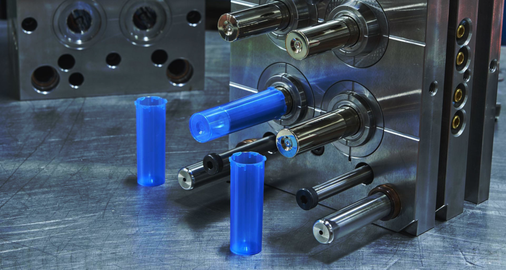
Industrial Projects
Applications:
Multi-cavity injection molds, die-casting inserts for automotive lighting, and stamping die assemblies.
Examples of technical challenges:
15° tool angles eliminate EDM, cutting mold lead time by 40%
0.005mm lens curvature consistency across 500+ cycles with 4-axis polishing
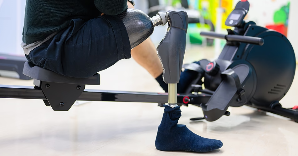
Medical Devices
Applications:
Porous titanium spinal cages, cobalt-chromium knee joint femoral components, and endoscopic tool shafts.
Examples of technical challenges:
0.03mm porous spinal implants with 5-axis micro-milling
Biocompatible mirror finishes (<0.1μm Ra) using 4-axis C-axis grinding
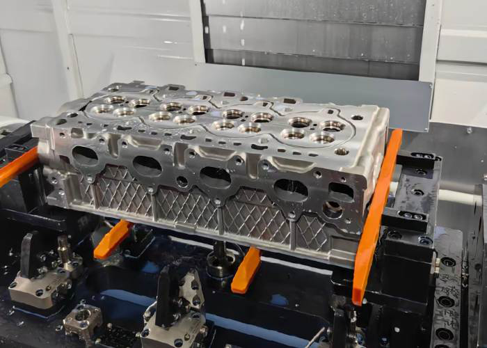
Automotive Manufacturing
Applications:
High-pressure fuel injector nozzles, aluminum EV battery trays with integrated cooling channels, and turbocharger turbine housings.
Examples of technical challenges:
±0.005mm fuel injector channel tolerances
40% faster EV battery tray milling via 4-axis vibration-dampened toolpaths
Aerospace Engineering
Applications:
Titanium engine mounts, composite material radar domes, and turbine blade tip seal grooves.
Examples of technical challenges:
0.2μm Ra radar dome surfaces
Hardened Inconel blade slots needing 4-axis 17° tilt-angle machining
4-Axis & 5-Axis CNC Machining FAQs
A 5-axis CNC machine utilizes programmed instructions to control the movement of the cutting tool and workpiece, the machining process starts with creating a 3D CAD model of the required parts, then it is exported into CAM software to get a G-code, which guides the operation of the machine. The G-code will contain tool paths that are generated according to the part geometry, the cutting tool will move along linear axes, and the worktable along rotational axes, 5 faces of a workpiece can be made in one setup.
Design and programming: the first step involves designing a part or component using CAD software and then translating it into a CAM program that generates the tool path to be used.
Material preparation: select the right material and make it prepared for machining, including cutting it into a roughly required shape and cleaning it.
Set-up: securely mount the material onto the machine bed or fixture and load the cutting tool into the spindle. The 5-axis machine should be programmed with the tool paths and machining parameters.
Machining: start the machine, and set the spindle rotates at high speeds and the cutting tool moves along the programmed tool path, cutting away material to create the part.
Inspection: when the 5-axis machining is completed, inspect the dimensions, surface finish and other specifications of the part using various instruments.
Based on the movement of the spindle head and worktable, the 5-axis CNC machines can be classified into three major types.
– Head/Head 5-axis machines: the rotational axes are located in the head, this type of 5-axis machine configuration is more suitable for producing large and heavy parts.
– Head/Table 5-axis machines: one rotational axis in the head and another one in the rotary table, the revolving of the axis in the head is restricted and the rotary shaft in the table has a wider range. The rotation of the workpiece has no limit and the number of parts it can manufacture is limited.
– Table/Table 5-axis machines: both the rotary axes are located in the table, and the head does not move. This type of configuration is ideal for producing undercuts and less for large or heavy parts.
In 5-axis CNC machining, there are five axes of motion that the cutting tool can move along. These are typically labeled with letters A, B, C, X, and Y, although the specific labels may vary depending on the machine manufacturer and software used.
- X-axis: This axis refers to the horizontal movement of the cutting tool along the length of the workpiece.
- Y-axis: This axis refers to the horizontal movement of the cutting tool along the width of the workpiece.
- Z-axis: This axis refers to the vertical movement of the cutting tool up and down along the height of the workpiece.
- A-axis: This axis refers to the rotation of the cutting tool around the X-axis. This is sometimes referred to as the "tilt" axis.
- B-axis: This axis refers to the rotation of the cutting tool around the Y-axis. This is sometimes referred to as the "swivel" axis.
– Number of axes: 3-axis CNC machines have movement in three axes (X, Y, and Z), while 5-axis CNC machines can move in five axes (X, Y, Z, A, and B). This additional degree of freedom allows for more complex and precise cuts.
– Flexibility: 5-axis CNC machining offersgreater flexibility than 3-axis because they can approach the workpiece from any angle and can machine complex geometries in a single setup. This reduces the need for multiple setups and improves accuracy.
– Efficiency: 5-axis machining centers areusually more efficient than 3-axis machines for machining complex parts. With 5-axis machines, multiple operations can be performed simultaneously, reducing the machining time and increasing productivity.
– Precision: 5-axis CNC service can produce parts with higher precision and accuracy than 3-axis machines. The additional axes of motion allow for more precise control over the cutting tool and the workpiece, resulting in tighter tolerances and smoother surface finishes.
– Cost: 5-axis CNC machining is generally more expensive than 3-axis due to their added capabilities and complexity.
Our 4-axis rigidity control protocol combines:
AI-powered feed rate adjustment based on real-time vibration sensors
Modular tool extensions (L/D ratio up to 12:1) for mold cores >150mm deep